33kv Substation Single Line Diagram Pdf
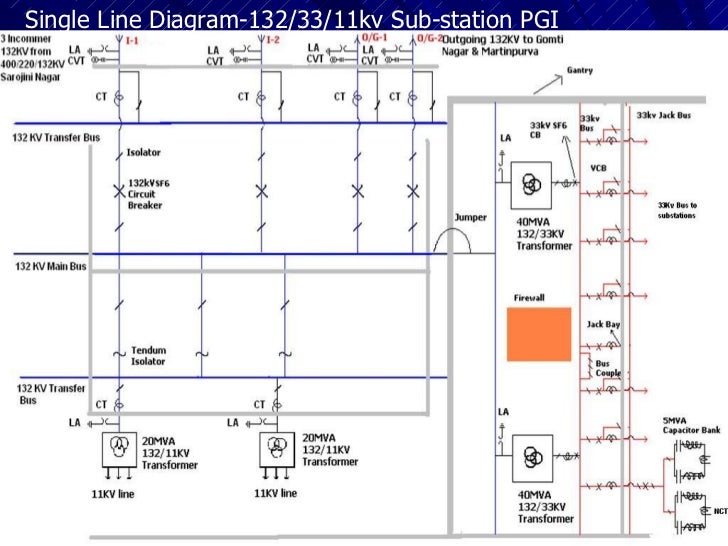
- A transformer is connected to main bus though a bus coupler. The mainbus has total capability of 160 MVA for 33 KV, which is subdivided into two transformercapacity of 80 MVA (40MVA+40MVA) parallel connected for 33KV and other two transformercapacity of 80KV (40KV+40KV) are parallel connected for substation.
- DISTRIBUTION SUBSTATION LAYOUT 1. Single source, single feeder substation The one-line diagram of a single-source, single-feeder substation with the minimum equipment used. A bypass switch is provided so service can continue during circuit breaker maintenance. The probability of a fault during circuit breaker maintenance.
Free download song of film jhankaar beats 2016. The main bus has total capability of 160 MVA for 33 KV, which is subdivided into two transformer capacity of 80 MVA (40MVA+40MVA) parallel connected for 33KV and other two transformer capacity of 80KV (40KV+40KV) are parallel connected for substation. A single line diagram would be better. Antonio DIAZ. Aug 15, 2018.
kV substation single line diagram Single Line Diagram, Design. Visit . General power substation diagram relevant to MV and LV distribution on board. SINGLE LINE DIAGRAM OF /33 KV GRID SUB – STATION BETTIAH. KV Transfer Bus. KV Main Bus. 33 KV Main Bus. 20 MVA. ABB Make. Tr. No. STRACTURAL NETWORK OF /33 KV SUB STATION FOR /33 KV SUB . SINGLE LINE DIAGRAM SHOWING INSTALLATIONS, REMOVING AND.
| Author: | JoJotaur Vulkree |
| Country: | Malaysia |
| Language: | English (Spanish) |
| Genre: | Software |
| Published (Last): | 14 March 2008 |
| Pages: | 463 |
| PDF File Size: | 5.98 Mb |
| ePub File Size: | 2.44 Mb |
| ISBN: | 599-7-67352-603-2 |
| Downloads: | 19909 |
| Price: | Free* [*Free Regsitration Required] |
| Uploader: | Shaktigore |
This functionality may be useful, for example, in illustrating the many issues associated with industry restructuring. The control of generation, transmission, distribution and area exchange are performed from a centralized location. Facebook Linkedin Google Plus Twitter.
Single Line Diagram of 11/ KV Switchyard

The pie charts associated with each transmission line, provide the student with an indication of transmission line loading. A power system network usually consists of component such as buses, transmission lines, generators and loads. The 11 KV bus feed the power to different 11 KV feeders. The power is then fed into a 33KV bus from which different loads were tapped. Generator bus is defined as any bus excluding the slack bus with a generator connected to it.
It is very necessary to carry out power flow analysis for satisfactory operation of the power system.
The results are used to evaluate the line or transformer loading and the acceptability of bus voltages. The main objective of this thesis is to simulate and analyze the KV Substation.
Simulation and Analysis of 220kV Substation
The power flow lne is used to evaluate the bus voltage, branch current, real power flow, reactive power flow for the specified generation and load conditions. This program computes the voltage magnitude and angle at each bus in a power system under balanced three-phase steady-state conditions. Power flow study also known as load flow constitutes an important part of power system analysis and design of any power system network.
The different kinds of faults are also simulated at various buses of the substation. The power loss of existing grid totalled To minimize these voltage violations, shunt capacitor compensators were placed at affected buses, resulting in a network with a minimum bus voltage of 0.
At its core is a comprehensive, robust Power Flow Solution engine capable of efficiently solving systems of up to 60, buses.
The load is supplied at various voltage levels.
By doing the power flow analysis in the Power World Simulator we estimate the real and reactive power flows, power losses in the entire network and phase angle using Power World Simulator. Each transformer has 15 MVA rating.
Electrical Design Of /33KV Substation EEP
Premium Membership Get access to premium electrical guides, technical articles and much more! Related article at PubmedScholar Google.
Generator 1 was set up to be the slack generator i. In load flow studies, there are three types of bus, slack bus, generator bus and load substatin. The power-flow computer program sometimes called load flow is the basic tool for investigating these requirements.
Now, this KV bus step downs voltage at 66 KV and KV for the transmission of power by using step down transformer. The load may be residential, industrial or commercial.
Experiments and interviews with system engineers are also discussed to measure the applicability of voltage contouring as an add-on to practical Energy Management Systems. A load in a power system context is defined as devices that consume power in the network. Bus represents reference node during calculation or simply nodes that are used in nodal analysis. The load centres are usually located away from generating stations.
The resulting bus voltages and phase angles are shown on the one-line diagram. The five parameters which are used for load flow analysis are voltage magnitude, voltage angle, real power, reactive power and admittance.
The animated results of this load flow are shown in Figure. The transformers used are transformer number 3, 4, 6. Depending on the requirement the loads are switched on and off. The blue line indicates the 66 KV bus section.
In practical field, system eubstation carryout load flows on a daily basis with varying system configurations, load patterns and generating conditions to understand the behaviour of the system at different operating conditions.
For this example, the resistance of each transmission line was not included, only the reactive component. Starting from the generating stations to the end users, voltage is needed to be stepped up and down several times in various substations.
There are four bus types in a power transmission network. Load, generation, and interchange schedule variations over time may be prescribed, and the resulting changes in power system conditions may be visualized. The approach to the modelling and the analysis of large-scale power flow solutions are presented in this thesis.
Most 10 Related
| Uploader: | Dorg |
| Date Added: | 21 March 2015 |
| File Size: | 61.10 Mb |
| Operating Systems: | Windows NT/2000/XP/2003/2003/7/8/10 MacOS 10/X |
| Downloads: | 3000 |
| Price: | Free* [*Free Regsitration Required] |
In Sub-Station, it is often desired to disconnect a part of the system for general maintenance and repairs. For the purpose of distribution it is first step down to V. It should be noted that low-voltage distribution system is sub-divided into feeders, distributors and service mains.
Is it stepped up to 33 kV at receiving station? Leave a Reply Cancel reply Your email address will not be published.
Professional in AutoCAD programming. Your email address will not be published.
Operation and commissioning of 33/11 kV power substation EEP
There are 3 substations within campus — Substation A, B, C. Biobele Alexander Wokoma Oct 03, No consumer is given direct connection from the feeders, instead consumers are connected to distribution network through their service mains. In Figure 1 C.
Power cuts are rare a There are circumstances where HVDC does make sense. Contents mainly covers electrical and electronics domains, our training experiences, eubstation concepts, small hobby and simulation based projects and updates about latest technologies.

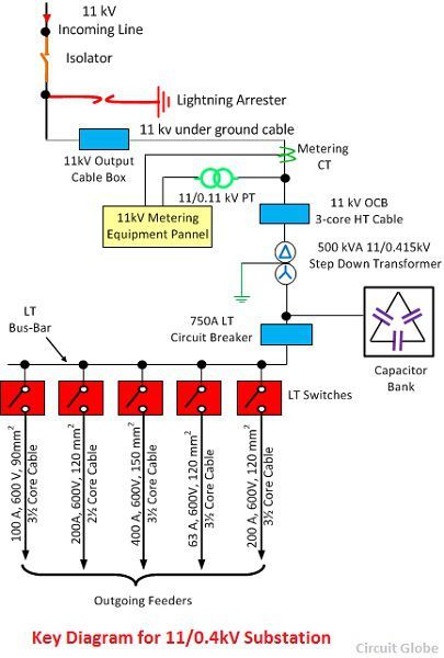
Single Line Diagram of 11kV Substation
Facebook Linkedin Google Plus Twitter. Dear Abdul Bari, The Voltage can always be stepped up and stepped down according to the necessity. Its kVA rating is not enough to drive both the departments as well as the hostel at the same time. Miracle Electronics 7 November at This is accomplished by an isolating switch or isolator.
Single Line Diagram of 11kV Substation - Meaning & Explanation - Circuit Globe

Actually it is consists of a feeder controlling room diaggram a switching yard. The main components are described below briefly: Thanks for the efforts.
33kv Line
Premium Membership Premium membership gives you an access to specialized technical articles and extra premium content electrical guides and doagram. Edvard Nov 13, VNIT 11kV indoor substation.
From just days and ni Manuel Bolotinha Nov 13, The 3-phase, 3-wire overhead high-voltage transmission line next terminates in step-down transformers in a substation known as Receiving Station R. The secondary transmission is also 3-phase whereas the distribution to the ultimate customer may be 3-phase or single- phase depending upon the requirements of the customers. Akbar Ali Khan Jun 12, Facebook Linkedin Google Plus Twitter.
Whereas at night, the authorities give priority to water pumping and then to the mess and the hostel. Training Report on Bokaro Steel Plant.
Consumers whose demands wubstation 50 kVA are usually supplied from SS by special 3. We are a bunch of enthusiastic bloggers who love to pen down stuffs we learn in our engineering life. If it is done that way please anyone explain the reason.